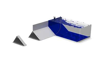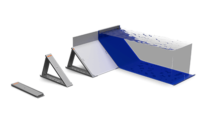
The C245 is the largest model in our Heavy Duty range, built for extreme flood protection needs. With an impressive 245 cm retention height, it offers performance that few barriers can match. Each section includes one support, one extension, four connection rods, and four aluminum panels, combining exceptional strength with efficient assembly.
Dam height
245 cm
Module width
C/C
122 cm
Deployment time
(100 m / 6 people)
2 h 55 min
Storage volume
(100 m)
13,3 m3
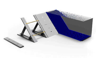
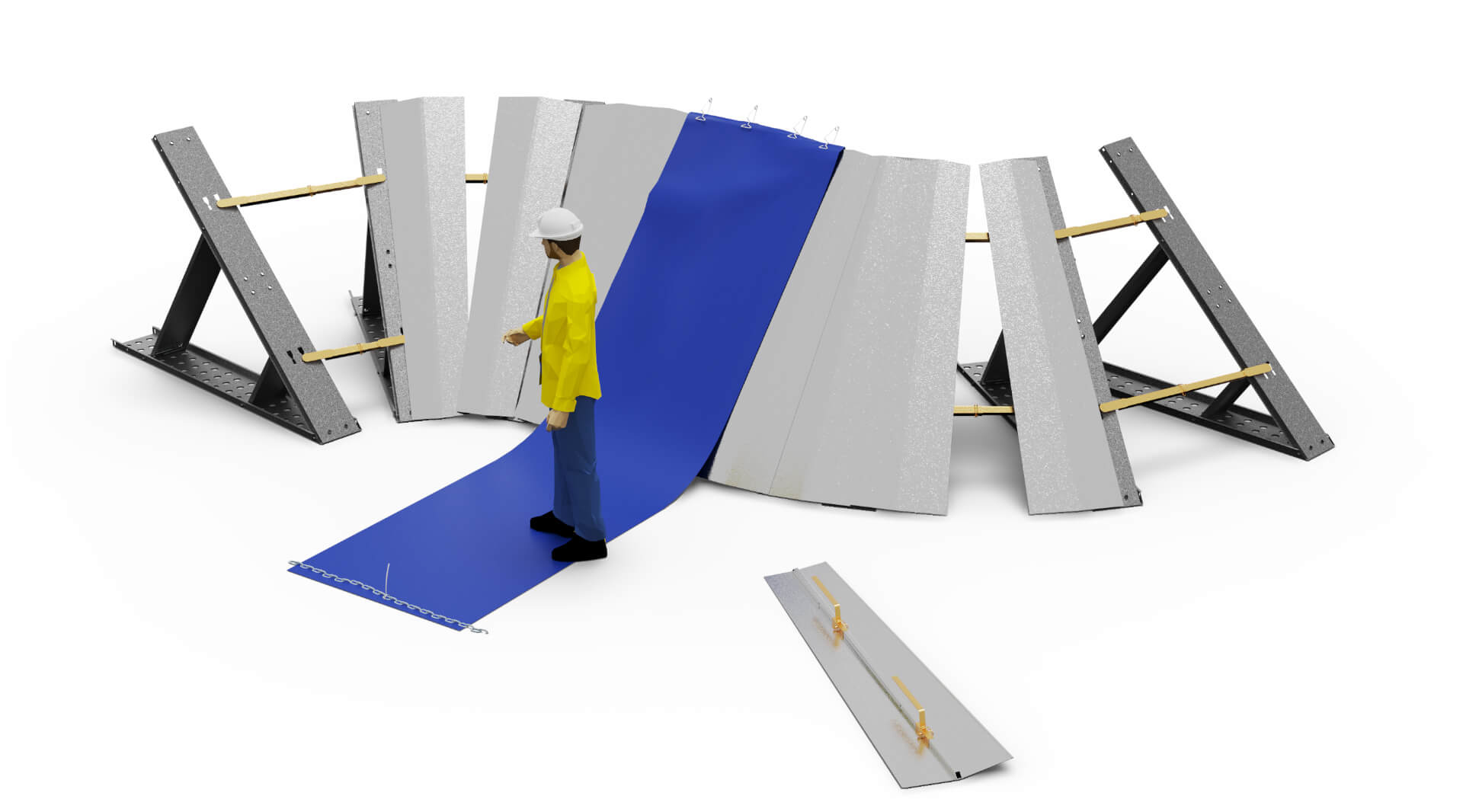
The C245 is the largest model in our Heavy Duty series, designed for extreme flood conditions where maximum protection is essential. Each section includes a robust support, an extension, four connection rods, and four aluminum panels — forming a strong, self-anchoring structure that reaches an impressive 245 cm retention height.
Like all Geodesign Barriers, the C245 sets up quickly without tools or groundwork, using the water’s own pressure to stay firmly in place.

| C184 Barrier support footprint (A) | 260 cm |
| C245 Extension folded footprint (B) | 340 cm |
| C245 deployed footprint without poly liner (C) | 367 cm |
| Maximum Water Column / Dam height (D) |
245 cm |
| Section Width (E) | 122 cm |
| Inclined Length (F) | 350 cm |
| Membrane ground length (G) | 580 cm |
| Poly liner width (F+G+20 cm) | 950 cm |
| Installation footprint (C+G) | 947 cm |
| Maximum Water Column / Dam height (A) | 152 cm |
| Set up time 100 metres by 6 workers | 2 h 10 min |
| Certifications | FM Approval ANSI 2510-2020 |
| Section Weight | 140.8 kg |
| Water Flow Resistance | 4 m/s |
| Extendable | +15 cm |
| Factor of safety | 1.5 |
| Load / section | -- kN |
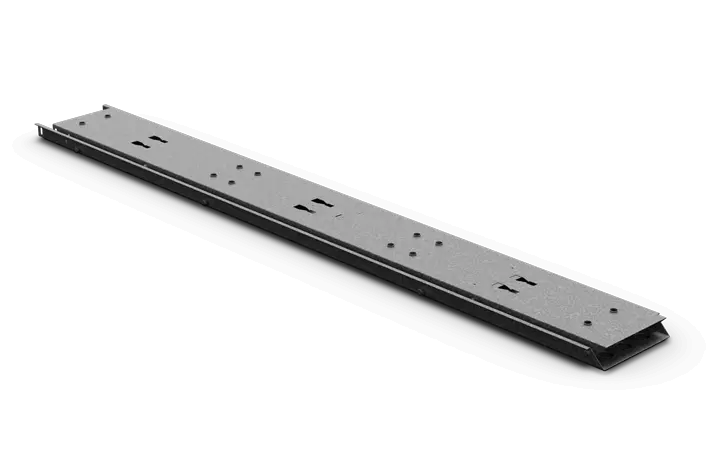
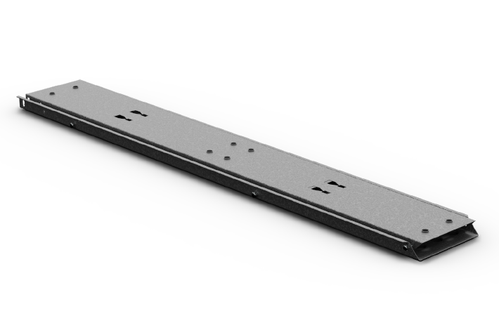
| Material | High strength low alloy steel |
| Dimensions | L 223 x W 32 x D 7,6 cm |
| Weight | 40 kg |
| Quantity / module | 1 pc |

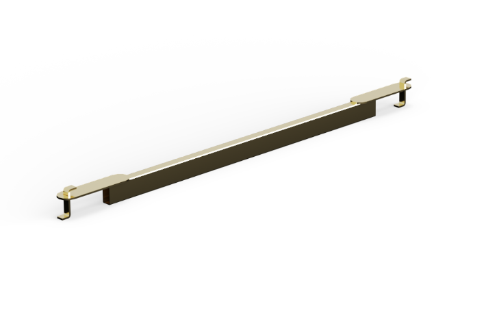
| Material | High strength low alloy steel |
| Dimensions | L 324 x W 32 x D 8,0 cm |
| Weight | 23 kg |
| Quantity / module | 1 pc |
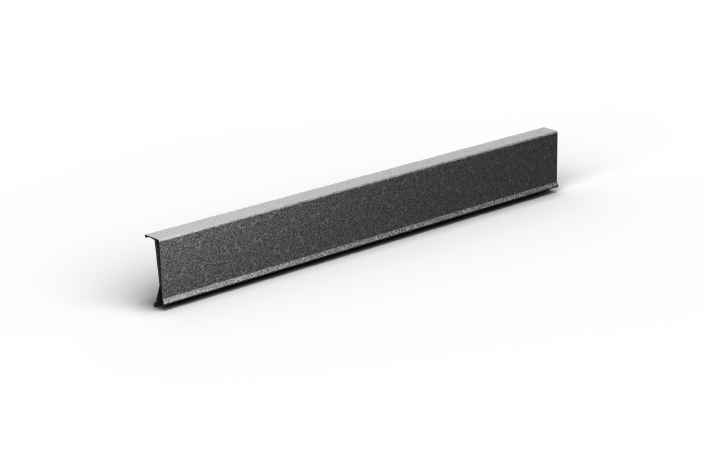
| Material | High-strength steel |
| Dimensions | L122 x W5 x D7 cm |
| Weight | 3 kg |
| Quantity / section | 2 pcs |
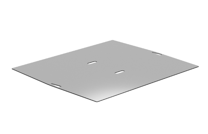
| Material | Aluminium Checker Plate |
| Dimensions | L120 x W107 x T0.7 cm |
| Weight | 17 kg |
| Quantity / section | 2 pcs |

| Material | PVC coated Low Density Polyethylene |
| Dimensions | L33 x W4.5 m - 420 g/m2 |
| Weight | 62 kg per roll |
| Quantity / section | 1.2 m / 0.037 roll |

| Material | Galvanized Steel DIN763 |
| Dimensions | L5 m x 12mm links excluding carabiners |
| Weight | 11.3 kg |
| Quantity / section | 3 m / 0.58 pcs |

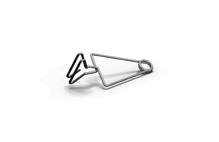
| Material | Nylon |
| Dimensions | L38 cm |
| Weight | 0.001 kg |
| Quantity / section | 2 pcs |
| Material | High Strength low alloy steel |
| Dimensions | L97 x W12.5 cm |
| Weight | 3.75 kg |
| Quantity / section | 1 pc |
The C152 Heavy Duty flood barrier offers maximum flexibility with the ability to turn in 15-degree increments. Our innovative design utilizes adjustable connection rods and specially designed corner elements to allow for quick and easy assembly of hearing sections.
Not only can the C152 Heavy Duty barrier be built to suit a variety of angles, but our specially designed corner elements can be used for both outer and inner turns, making the process even more streamlined.
| Maximum Water Column / Dam height (A) | 152 cm |
| Set up time 90 degrees by 6 workers | 55 min |
| Section Weight | 78.4 kg |
| Turning radius / section | 15 degree |
| Extendable | No |
| Upper arc length (A) | 250 cm |
| Lower arc length (B) | 470 cm |
| Membrane length (C) | 805 cm |
| Turning radius | 515 cm |
| Sealer clips | 9 |

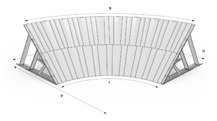
| Turning radius (F) | 705 cm |
| Lower inner arc length (I) | 535 cm |
| Lower outer arc length (H) | 1105 cm |
| Upper arc length (G) | 905 cm |
| Membrane length (G) | 905 m |
| Sealer clips | 18 |
| Material | High Strength low alloy steel |
| Dimensions | L219 x W32 x D6.5 cm |
| Weight | 29 kg |
| Quantity / 90 degree corner | 3 pcs |

| Material | High Strength steel |
| Dimensions | min. L794 mm max. L1189 mm |
| Weight | 3.9 kg |
| Quantity / 90 degree corner | 6 pcs |
| Material | Zinc coated, galvanized steel |
| Dimensions | L215 x W50/32 |
| Weight | 12 kg |
| Quantity / 90 degree corner | 9 pcs |
| Material | PVC coated Low Density Polyethylene |
| Dimensions | L33 x W4.5 m - 420 g/m2 |
| Weight | 62 kg per roll |
| Quantity / 90 degree corner | 8 m |
| Material | Galvanized Steel DIN763 |
| Dimensions | L5 m x 12mm links excluding carabiners |
| Weight | 11.3 kg |
| Quantity / 90 degree corner | 9 m |
| Material | Nylon |
| Dimensions | L38 cm |
| Weight | 0.001 kg |
| Quantity / 90 degree corner | 16 pcs |
| Material | Steel |
| Dimensions | L17 cm |
| Weight | 0.08 kg |
| Quantity / 90 degree corner | 3 pcs |
Our step-by-step instructions are designed to guide you through the process of setting up your system quickly and easily. Even if you're new to the C152, our instructions are straightforward and easy to follow.
While we're confident that anyone can set up the C152 using our manual, we do recommend training and consultation for the best possible outcome. These additional resources can help you optimize your setup and ensure that everything runs smoothly.
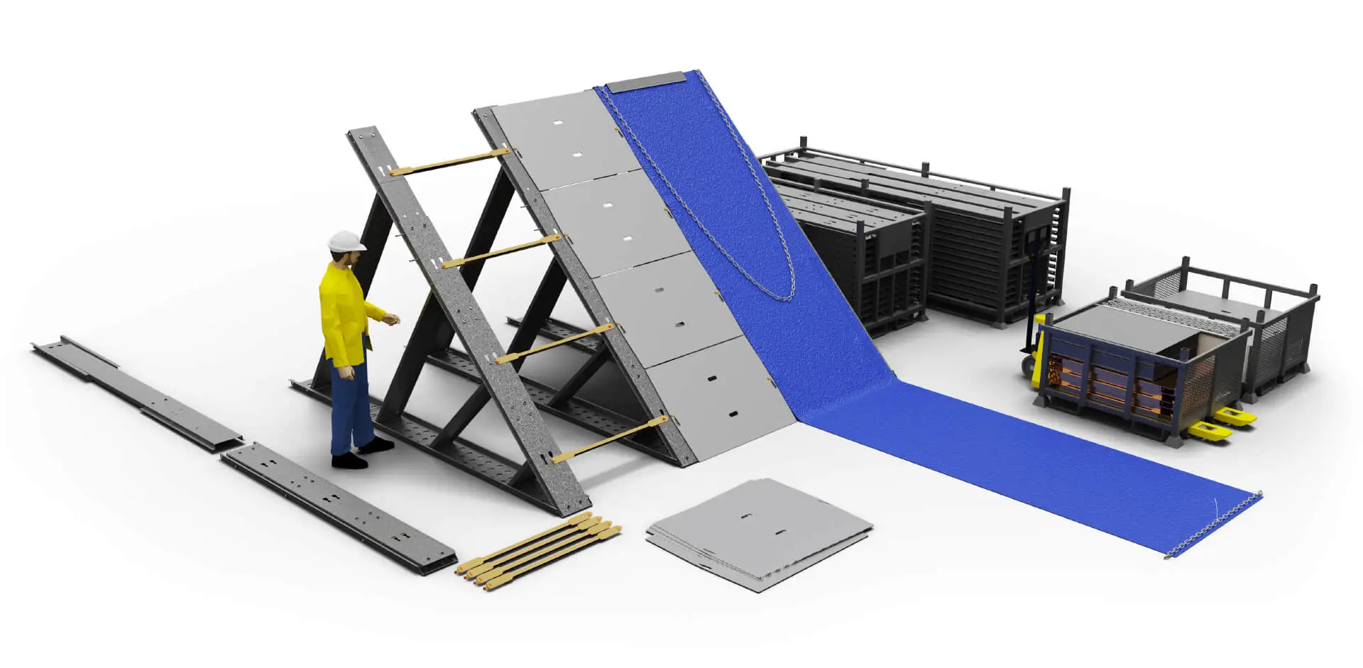
Place the C72 | C184 Barrier Supports and C96 | C245 Extensions 4 ft / 122 cm apart. Use Link Bars to gauge the distance.
Errect the C96 | C245 Barrier Extension. Lift the support beam up and push the Extension in place from behind.
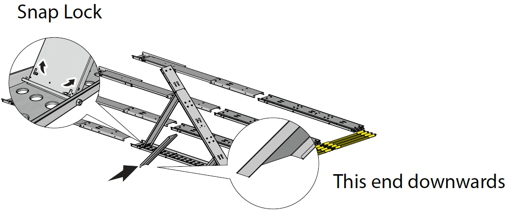
Secure upright position using the Snap Lock on outer support beam. Put the detached middle support beam in place.
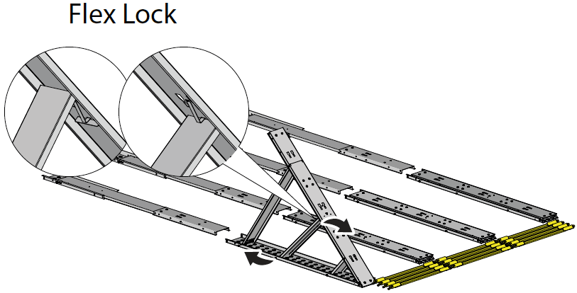
Attach the middle support beam by letting the top part slide through the Flex Lock.
Connect the C72 | C184 Barrier Supports using Link Bars on the top and bottom row.

Erect the C96 | C245 Barrier Extension. Lift the support beam up and push the Extension in place from behind.
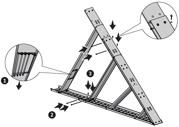
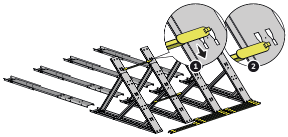
Secure the C96 | C245 Barrier Extension to C72 | C184 Barrier Support using the 4 Security Rods placed on the inside of the support beam of the Extension.
If installed on concrete

Prepare installation of Concrete Anchor. Drill a hole using a Hammer drill. Screw on the Concrete Anchors into the ground. Leave a distance of 1/2 in / 1.5 cm between top of the Concrete Anchor and the bottom beam.
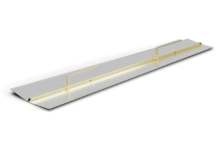
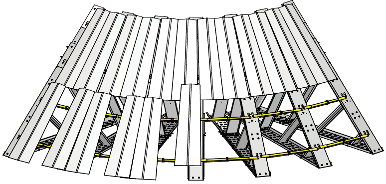
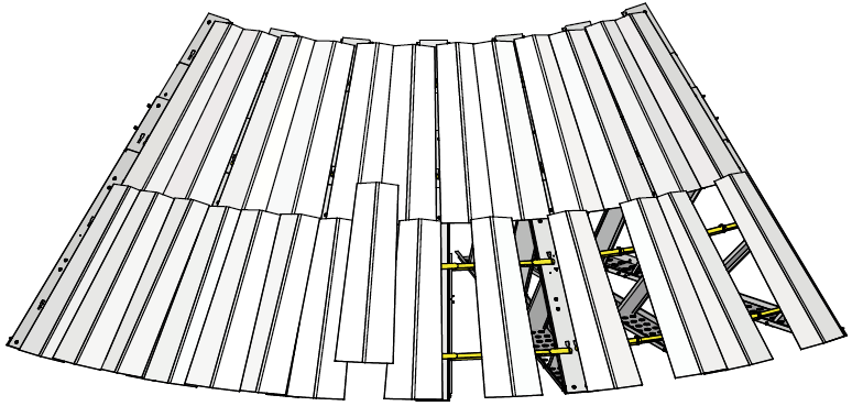
Connect the extensions using Link Bars. Mount the Alu Panels 860 onto the two top rows of Link Bars by sliding the key hole cut out over the protruding part of the Link Bar.
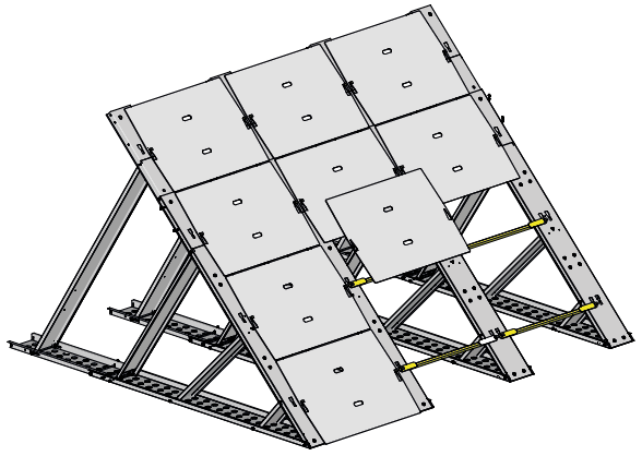
Attach the last row of Link Bars and mount the rest of the Alu Panels 860.
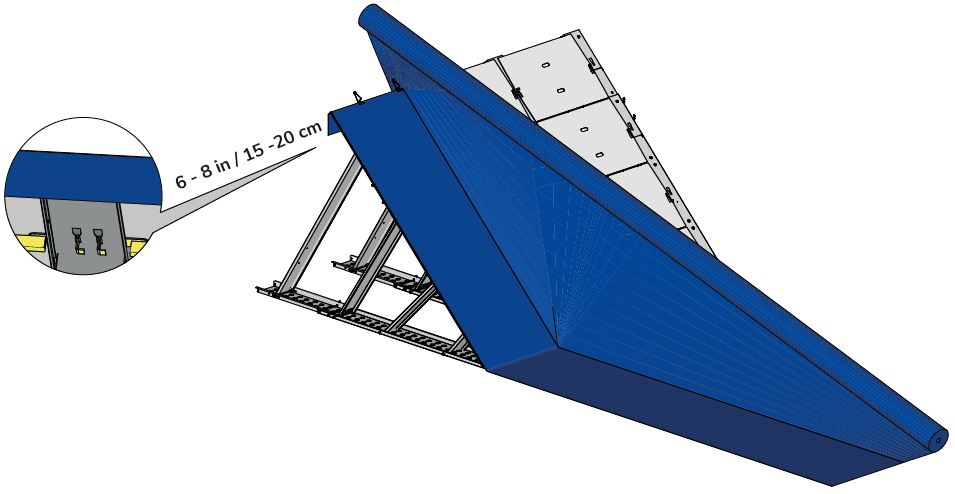
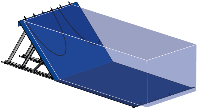
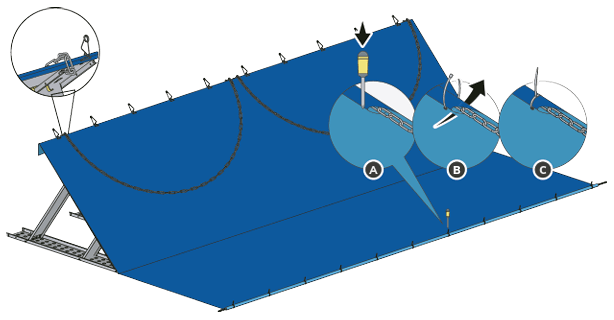
Roll out the 31 ft | 9.5 m wide Poly Membrane and secure with two Sealer Clips per section, along the top edge. Ensure that there is between 6 - 8 in / 15 - 20 cm overlap at the back of the Barrier.

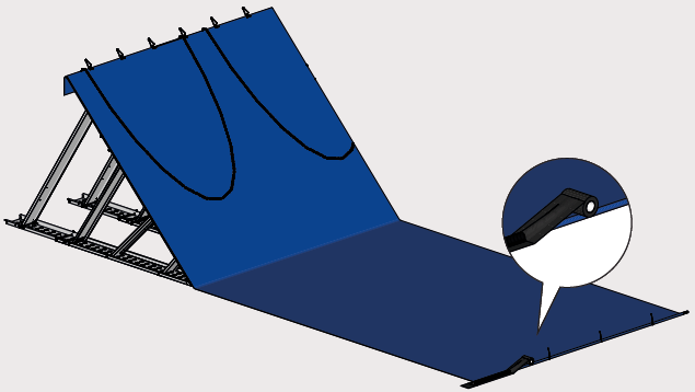
Connect the Chain lengths with the carabiners and place them along the outer edge of the Poly Membrane. Wrap the Chain in the Poly Membrane – no more than 2 turns. Secure the wrapped Chain with Cable Ties using the small holes in the Poly Membrane – one every 3.3 ft / 1 m.

Hang the garland Chain on to the inclined part of the Barrier. Use the carabiner hook to secure the Chain to the C96 | C245 Barrier Extension.
If installed on concrete
Seal the Poly Membrane to the ground using 8 in / 20 cm wide Sealing Tape.
Adjust Sealer Clips when the water enters the Barrier to relax the Poly Membrane. Squeeze out air pockets under the Poly Membrane by gently stepping on them.
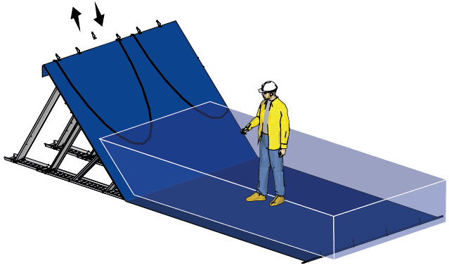
Installed and self-anchored as rising water presses the barriers to the ground.
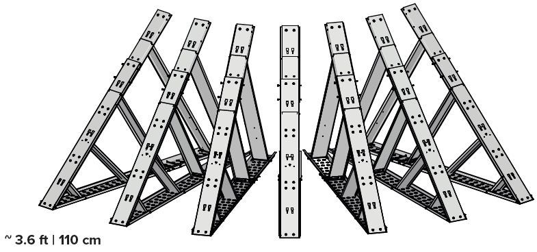
Place seven unfolded and secured C96 | C245 Metal Supports in a 90° arc approx 3.6 ft | 1.1 m apart. The supports can be placed with a closer distance between if needed.
Begin connecting the C96 | C245 Metal Supports using two Adjustable Link Bars SMALL (ALB-Short). Insert the ALB-Short through the two top keyhole cuts on the C96 | C245 Metal Supports and slide down to lock. Fix each ALB-Short at a suitable length with the Pin Lock.
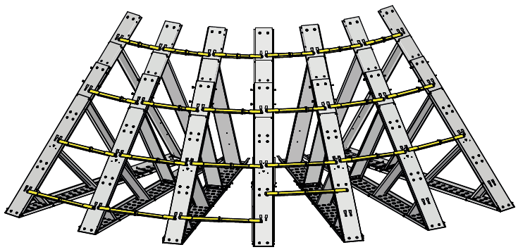
Continue connecting the C96 | C245 Metal Supports by attaching the Adjustable Link Bars LONG (ALB-Long) through the two lower keyhole cuts and slide down to lock. Fix each ALB-Long at a suitable length with the Pin Lock.
Assemble the Corner Element LARGE (CE-Large). The wide part of the CE-Large should face downwards. Attach the handles to the top holes of the CE-Large. Fix using the Pin Lock.
Place two CE-Large onto the two top ACR. Slide them down into position next to each other.
Place another two CE-Large onto the two lower ACR. Slide them down into position – one to the left and one to the right. Leave a gap in between.
Fill the gap by sliding a third CE-Large on top of the other two.
Start rolling out the membrane from the beginning of the arc. Fold over the top by 8 in | 20 cm. Fix the position of the membrane to the C96 | C245 outer corner with a Sealer Clip.
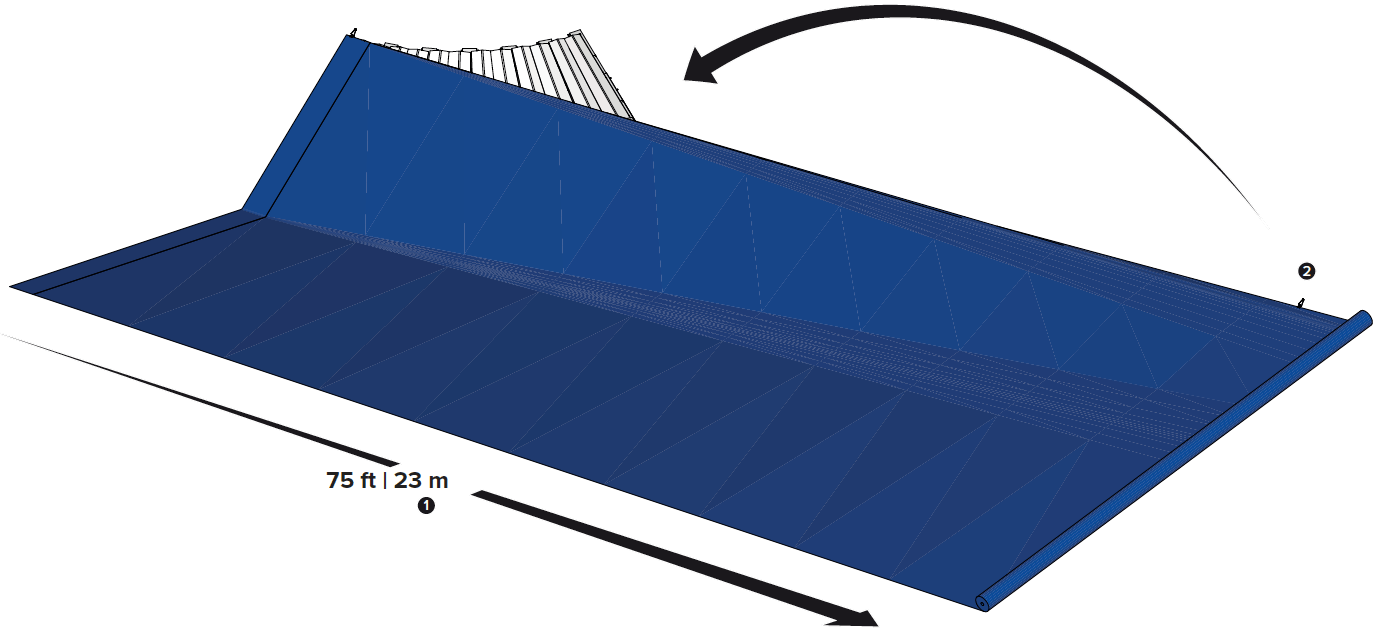
Extend the membrane 75 ft | 23 m out from the C96 | C245 outer corner. Fold the extended membrane back.
Seal the folded plastic membran to the barrier with sealer clips.
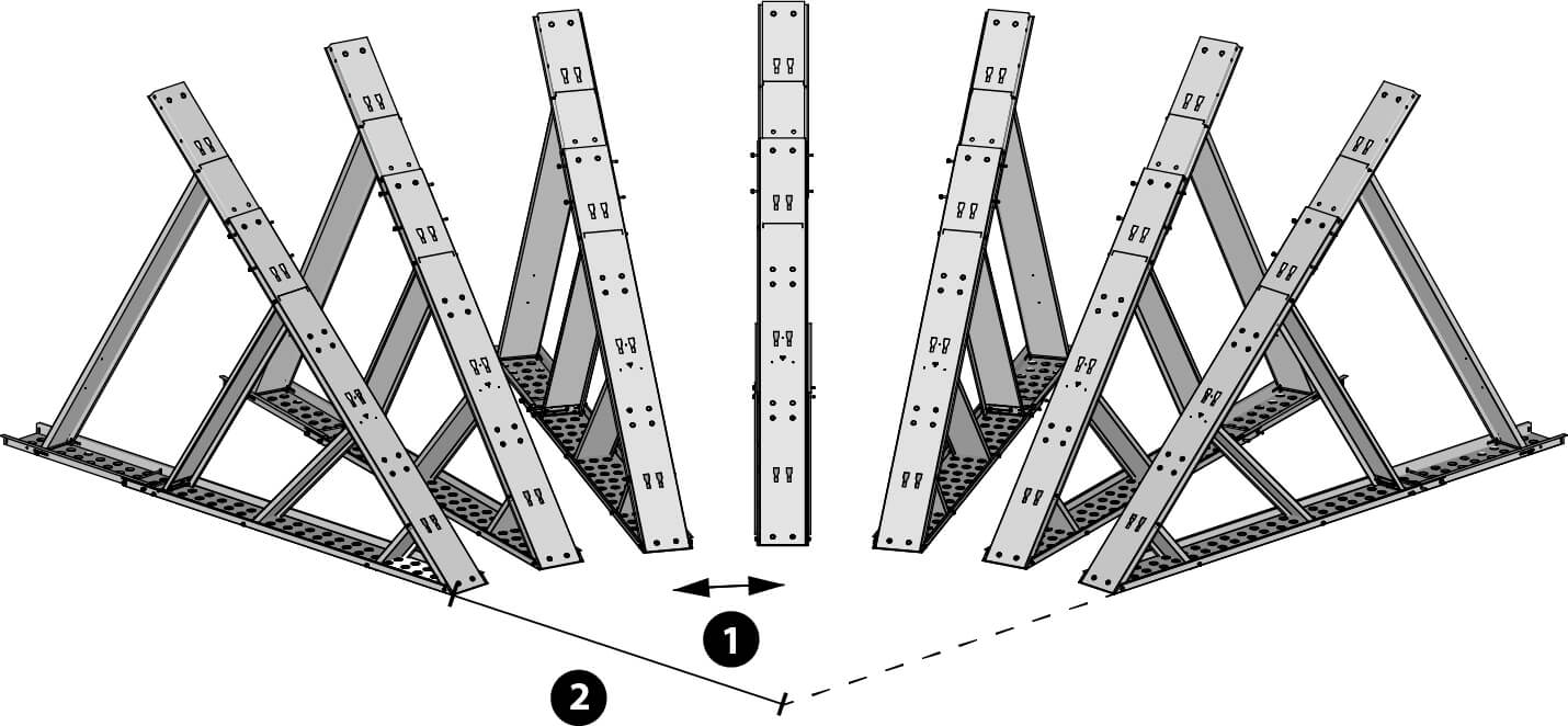
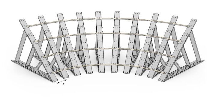
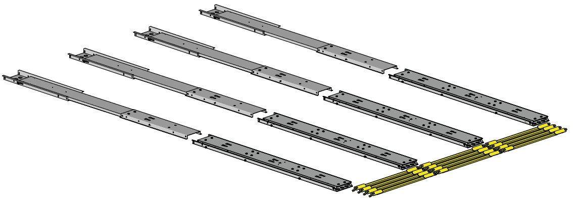
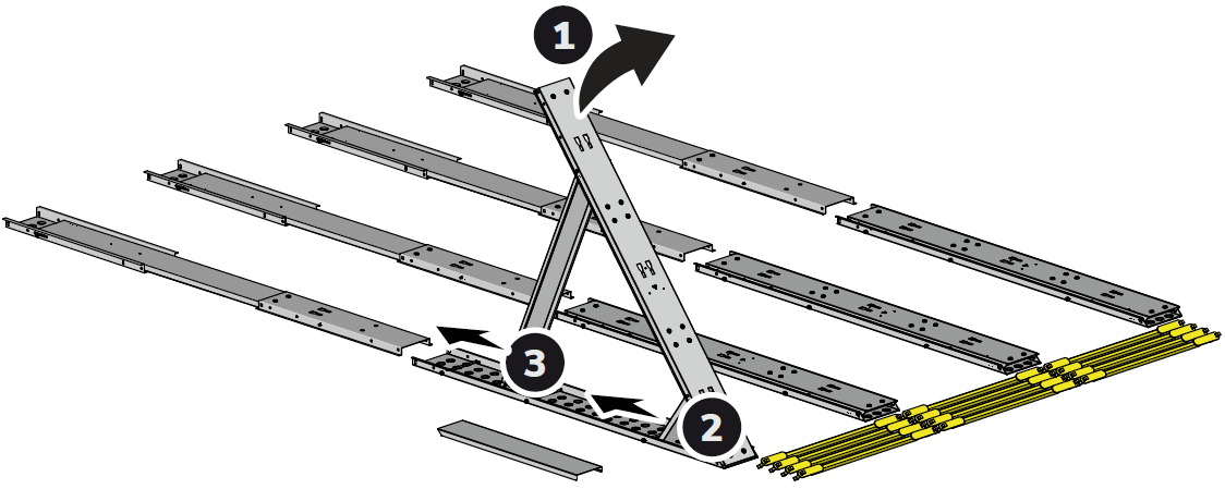
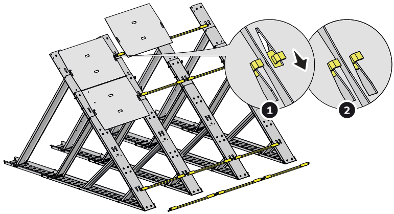
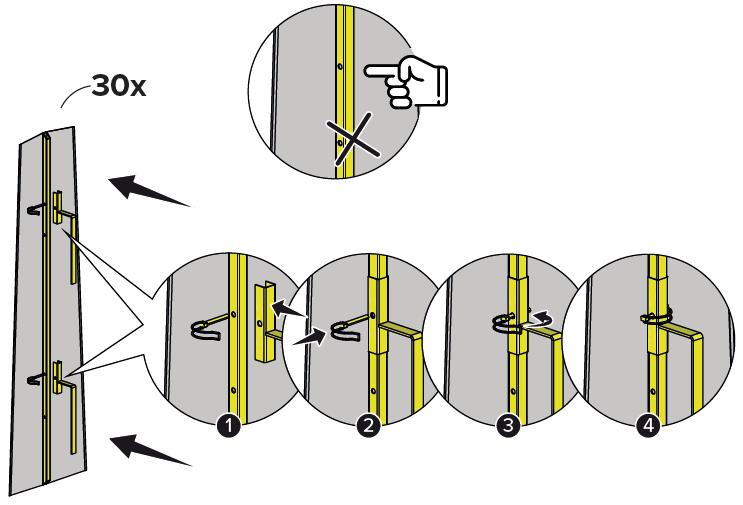
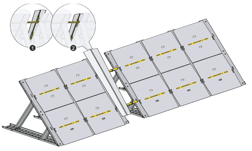
Place six unfolded and secured C245 Metal Supports in a 90° arc, each set at approximately a 15° angle and spaced 0.6 m apart at the base ❶.
The two outermost supports should form an approximate 90° angle to each other. The distance ❷ from the base of the first support to an imaginary extension line of the last support should be approximately 2.5 m.
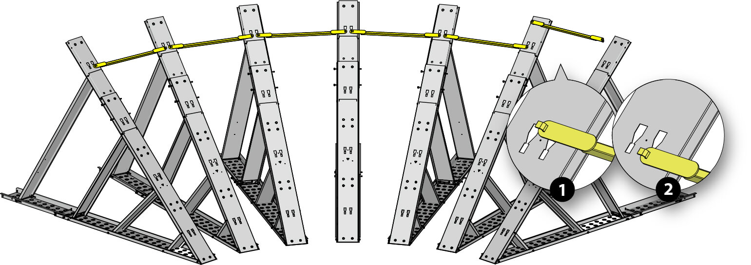
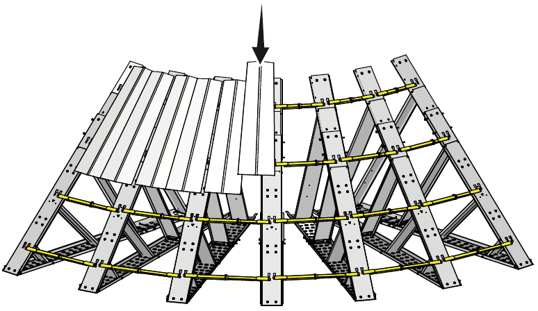
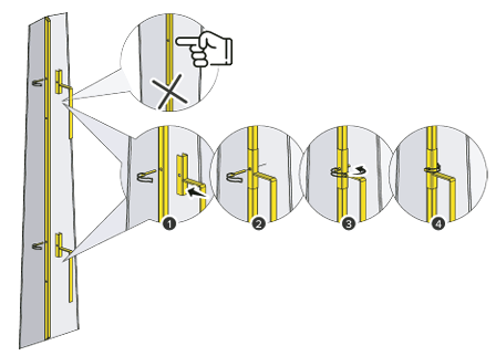
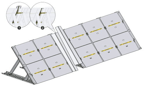
Begin connecting the C245 Metal Supports using Link Bar 1219 (LB).
❶ Insert the LB into the top keyhole slots of the supports, then
❷ slide it downward to lock into place.
Begin connecting the C245 Metal Supports using Link Bar 1219 (LB).
❶ Insert the LB into the top keyhole slots of the supports, then
❷ slide it downward to lock into place.
Begin connecting the C245 Metal Supports using Link Bar 1219 (LB).
❶ Insert the LB into the top keyhole slots of the supports, then
❷ slide it downward to lock into place.
Begin connecting the C245 Metal Supports using Link Bar 1219 (LB).
❶ Insert the LB into the top keyhole slots of the supports, then
❷ slide it downward to lock into place.
Begin connecting the C245 Metal Supports using Link Bar 1219 (LB).
❶ Insert the LB into the top keyhole slots of the supports, then
❷ slide it downward to lock into place.
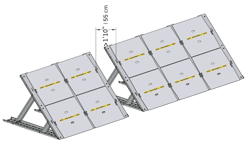
Build the two approaching C60 | C152 barriers in a line. Stop when the distance between the barriers is smaller than one full section (4 ft | 121 cm)
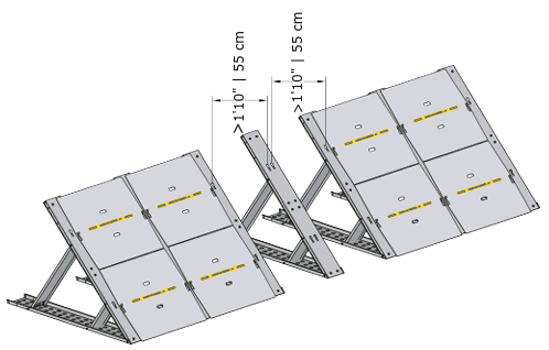
If the distance in the previous step is smaller than 1'10" | 55 cm, remove one section. Then create two adjustable sections with equal width.
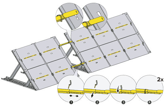
Use adjustable Link Bars to patch the section or sections where the two barrier lines meet.
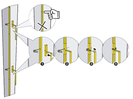
Assemble the C60 | C152 Corner Element. Make the narrow part of the Corner Element point down. Attach the handles and align to the top holes of the Corner Element. Fix using Pin Lock.
Start covering the adjustable section with the C60 | C152 Corner Element. Place it on the adjustable Link Bars with the wide part up and slide down in to position.
Assemble another C60 | C152 Corner Element. This time make the wide part of the Corner Element point down. Attach the handles and align to the top holes of the Corner Element. Fix using Pin Lock.
Continue cover the adjustable section with the Corner Element. Place it on the adjustable Link Bars with the narrow part up and slide down in to position. Continue in the same way by alternating the direction of the Corner Element up and down if additional Corner Elements are needed.
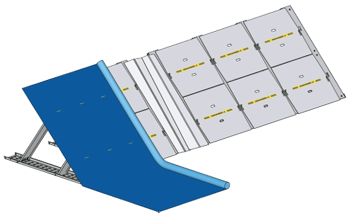
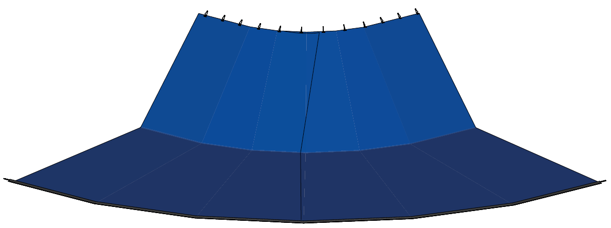
Seal the barrier with the included Geodesign Poly Membrane
Fix the Poly Membrane with Sealer Clips. Add Chain length at the bottom. Instructions for enclosing the Chain can be found in standard manual for C60 | C152 Straight section
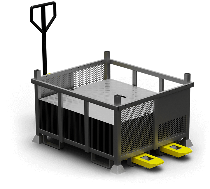
The C152 Heavy Duty System is shipped in durable, weatherproof metal crates designed for both delivery and long-term storage. Each crate is covered with a PVC hood to keep the contents dry and dust-free. These stackable crates are designed for space-efficient storage and can be easily moved with a manual forklift, offering flexible handling on-site.
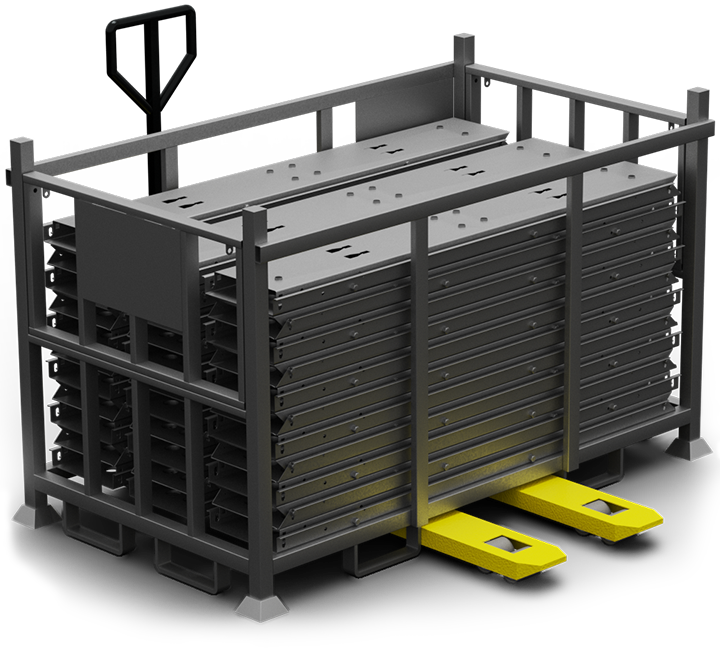
| Material | Galvanized Steel |
| Dimensions | L1.4 x W1.15 x H0.88 m |
| Weight | 1550 kg |
| Quantity / crate |
90 alu sheets |
| Material | Galvanized Steel |
| Dimensions | L2.4 x W1.15 x H1.2 m |
| Weight | 1220 kg |
| Quantity / crate |
39 supports |
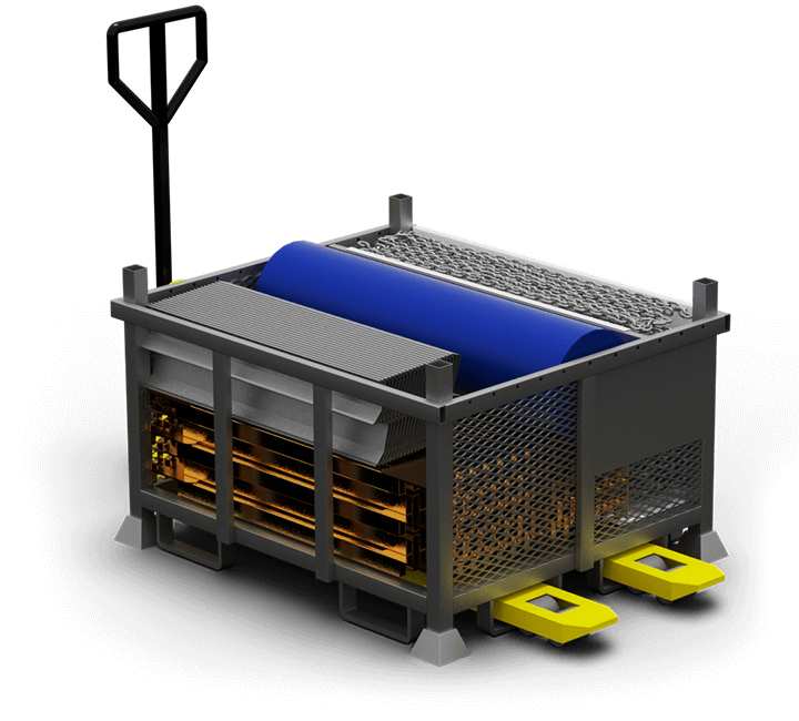
| Material | Galvanized Steel |
| Dimensions | L1.4 x W1.15 x H0.88 m |
| Weight | 750 kg |
| Quantity / crate |
Remaining components |
The C152 Heavy Duty system is efficiently packed in durable, stackable metal crates, all fitting neatly into a 20-foot container. This compact solution offers convenient storage and strategic placement, ensuring fast access and rapid deployment when needed. Simply position the container where it's required—no additional storage space is necessary.

| Combi crate: | 14 units |
| C152 support crate: | 9 units |
| Membrane shelf | 1 unit |
Discover how the C152 Heavy Duty Barrier can be your trusted solution for flood protection. Contact us today for expert guidance and a personalized quote tailored to your needs.